Explore / RFID Basics & Resources
Inductive and Backscatter Coupling
Passive tags do not have an active transmitter that communicates with the interrogator. They typically couple the transmitter to the receiver with either load modulation or backscatter, depending on whether the tags are operating in the near-field or far-field of the interrogator.
Coupling is the transfer of energy from one medium to another medium, and passive tags use it to obtain power and transfer data. The type of coupling used, inductive or backscatter (also known as radiative), depends on the frequency and the distance between the tag and the interrogator antenna.
Inductive coupling uses near-field effects, while backscatter coupling uses far-field effects. Near-and far-field effects are different mechanisms for transfer of energy in free space.
THE BOUNDARY BETWEEN THE NEAR-FIELD AND FAR-FIELD IS Λ/2Π (Λ – WAVE LENGTH)
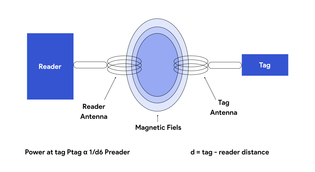
Within the near-field, the magnetic field intensity decays rapidly as 1/d3 (d = distance between the interrogator antenna and the tag).
When the magnetic field strength is translated into power available to the tag, the power attenuates according to 1/d6. The magnetic field strength is thus high in the immediate vicinity of the transmitting antenna, but its level is reduced to being negligible in the far-field.
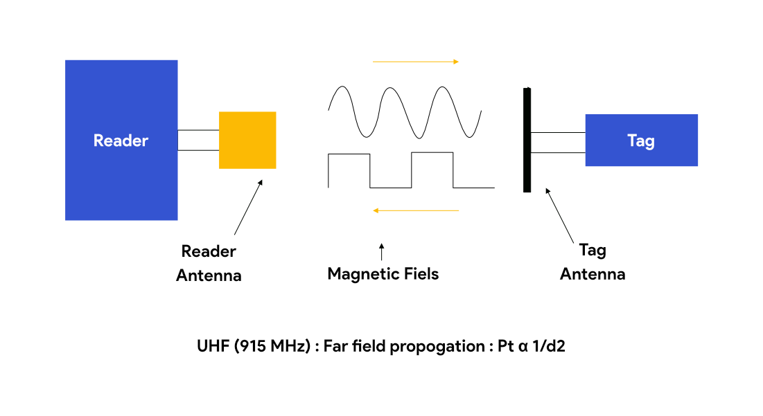
In the far-field the power at the tag is attenuated to 1/d2.
NEAR-FIELD/INDUCTIVE COUPLING
Inductive coupling refers to the transfer of energy from one circuit component to another through a shared magnetic field. A change in current flow through one device induces current flow in the other device. Inductive coupling favors low-frequency energy sources.
RFID systems operating at 125–135 kHz and 13.56 MHz operate in the near-field and use inductive coupling, while those operating beyond 100 MHz, such as 860–960 MHz and 2400 and 5800 MHz, operate in the far-field and use backscatter (radiative) coupling.

The wavelength of the frequency ranges used in inductively coupled RFID system (135 kHz: 2400 m; 13.56 MHz: 22.1 m) is much more than the conductor length in any standard interrogator antenna. It is also several times greater than the distance between the interrogator antenna and the tag antenna. Because of this, the electromagnetic field may be treated as a simple magnetic alternating field with regard to the distance between tag and antenna.
The interrogator communicates with the tag by modulating a carrier wave by varying the amplitude, phase, or frequency of the carrier. This modulation can be directly detected as current changes in the coil of the tag. The tag communicates with the interrogator by varying how much it loads its antenna. This in turn affects the voltage across the interrogator’s antenna. By switching the load on and off rapidly, the tag can create sideband frequencies, which are then coupled into the interrogator antenna.
For an RFID system operating at 13.56 MHz, the approximate distance at which the near-field zone ends is λ/2π, or 3.5 meters. Beyond this distance, the magnetic field is reduced so low that tags cannot be powered. Due to this, the typical read range for 13.56 MHz tags is less than 1 meter. The read distance depends on the size of the interrogator antenna. Typical handheld interrogators can read an electronic identity from about 2 inches. An interrogator with a large antenna can read a tag up to 2 feet away. Inductively coupled systems are not affected by water or human tissue but are sensitive to metal (conducting material) in the operating zone. Also, as the magnetic field has vector characteristics, the tag orientation influences performance of the system. Since inductive RFID systems are operated in the near-field, interference from adjacent systems is lower compared to radiatively coupled systems.
FAR-FIELD/BACKSCATTER COUPLING
As the electromagnetic wave travels away from the antenna, the magnetic field strength rapidly decays and its effect is negligible in far-field regions. Outside the radius of the near-field, the wave from the interrogator propagates outward, never giving energy back to the radiating element. This electromagnetic wave travels outward and encounters the antenna element in the tag. When electromagnetic waves encounter an object that has a dimension of half the wavelength or more, it gets reflected. The efficiency with which an object reflects electromagnetic waves is described by its reflection cross-section. Objects that are in resonance with the wave front that hits them, as is the case for an antenna at the appropriate frequency, for example, have a particularly large reflection cross-section.
Tags operating at UHF and microwave frequencies use far-field and couple with the interrogator using backscatter. The amount of energy received at the receiver decreases as an inverse of the square of the distance (d) between the interrogator antenna and tag (1/d2).

An electromagnetic field propagates outward from the interrogator’s antenna, and a small proportion of that field (reduced by free-space attenuation) reaches the tag’s antenna. The power is supplied to the antenna connections as high-frequency voltage, and after rectification by diodes it can be used to power the tag or activate or deactivate the tag. Some proportion of the incoming RF energy is reflected by the antenna and reradiated outward into free space. The amount of energy reflected depends on how well the antenna couples to the electromagnetic wave. RFID tags that use backscatter to reply to their interrogators have antennas that are designed to resonate well with the carrier signal emitted by the interrogator. The reflection characteristics of the antenna, its effective cross-section, can be influenced by altering the load connected to the antenna. To transmit data from the tag to the interrogator, a load resistor connected in parallel with the antenna is switched on and off in time with the data stream to be transmitted. By changing resonant properties of its antenna, the tag makes itself a good or poor reflector. This varies the strength of the signal reflected from the tag, creating a pattern that is detected at the interrogator as data. This technique is referred to as modulated backscatter.
Before the backscattered signal arrives at the interrogator antenna, it goes through forward and backward path loss, many types of interferences in both the directions, and absorption by the tag to power it. The reflected signal also travels into the antenna connection of the interrogator in the reverse direction from the original signal. It is decoupled using a directional coupler and transferred to the receiver input of the interrogator. The forward signal of the transmitter is to a large degree suppressed by the directional coupler.
Remember that radiative, backscatter, or far-field coupling is used by RFID systems operating at UHF and microwave frequency ranges.