Explore
How to Select a Correct Tag – Frequency
RFID tags are categorized according to the frequency at which they are designed to operate. Four primary frequency ranges are allocated by various government authorities for use by RFID systems.
• Low frequency (LF)
• High frequency (HF)
• Ultra high frequency (UHF)
• Microwave frequency (microwave)
All of these ranges are part of the frequency bands called Industrial, Scientific, And Medical (ISM) radio bands and were originally reserved for non-commercial use. Depending on the usage, the tags are designed to operate in any one of these ranges. The material of the object being tagged and the read range required are the main factors in selection of frequency. Objects with water content absorb frequencies in certain ranges but have no effect on frequencies in another range.
LOW FREQUENCY (LF) TAGS
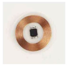
Low frequency range includes frequencies from 30 to 300 KHz but only 125 KHz and 134 KHz (actually, 134.2 KHz) are used for RFID. This range has been in use for RFID tags for animal tracking since 1979 and is the most mature range in use. It is available for RFID use all over the world. The tags in this range are generally called LF tags. They use near-field inductive coupling to obtain power and to communicate with the interrogator. The LF tags are passive tags (no battery and transmitter on the tag) and have a short read range of a few inches. They have the lowest data transfer rate among all the RFID frequencies and usually store a small amount of data. The LF tags have no or limited anti-collision capabilities; therefore, reading multiple tags simultaneously in the IZ is impossible or very difficult. The tag antennas are usually made of a copper coil with hundreds of turns wound around a ferrous core. They are expensive to manufacture, and tags using them are thicker than others at higher frequencies. The LF tags can be easily read while attached to objects containing water, animal tissues, metal, wood, and liquids.
LF tags have the largest installed base. They are used in access control, asset tracking, animal identification, automotive control, as vehicle immobilizers, healthcare, and various point-of-sale applications (such as Mobil/Exxon SpeedPass). The automotive industry is the largest user of LF tags. For example, in an automobile vehicle immobilizer system, an LF tag is embedded inside the ignition key. When that key is used to start the car, an RFID interrogator placed around the key slot reads the tag ID. If the tag ID is correct, the car can be started. If the ID is incorrect or no tag is found, the car cannot be started.

Example of LF Inlay
HIGH FREQUENCY (HF) TAGS
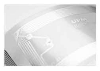
The high frequency range includes frequencies from 3 to 30 MHz but only one frequency, 13.56 MHz, is used for RFID applications. This frequency is now available for RFID applications worldwide with the same power level. Tags and interrogators using 13.56 MHz are generally called the HF tags and the HF interrogators. They, like the LF tags, also use near-field inductive coupling to obtain power and to communicate with the interrogator. HF tags are passive tags and have short read range, less than 3 feet. They have a lower data transfer rate than the UHF frequencies but a higher data rate than the LF. The HF tags may have anti-collision capability that facilitates reading of multiple tags simultaneously in the IZ. Since the read range of many HF tags and interrogators is small, they usually do not implement anti-collision. This reduces the complexity and cost. Some HF tags can store up to 4K of data. HF tags are more mature than UHF tags and many standards are in place.

Example of LF Inlay
HF tag antennas are usually made of a copper, aluminum, or silver coil with three to seven turns. They are easy to manufacture, and the tags are usually very thin, almost two-dimensional. HF tags are lower in cost due to simpler antenna design than LF tags. They can be made in different sizes, some less than a half inch in diameter. HF tags can be easily read while attached to objects containing water, tissues, metal, wood, and liquids. They are affected by metal objects in the close vicinity, however. HF interrogators are less complex than UHF interrogators and usually cost less than the latter.
Inductive coupling used by the HF interrogators uses magnetic flux to power and communicate with the tags. Magnetic flux is omnidirectional (not directional) and therefore it covers the entire area, surrounding its source evenly. That means there are no holes in its density. This makes HF tags an ideal choice for applications such as a smart shelf, for which the entire shelf area needs to be covered with magnetic flux so all the items on the shelf can be interrogated. Other applications of the HF tags include credit cards, smart cards, library books, airline baggage, and asset tracking. Due to the absence of restrictions on the use of the HF frequency and the popularity of smart cards, HF tags are currently the most widely used tags around the world.
NOTE: HF TAG HAS ANTENNA WITH 3 TO 7 TURNS OF COIL WHILE LF TAG ANTENNA HAS SEVERAL HUNDREDS OF TURNS.
ULTRA HIGH FREQUENCY (UHF) TAGS
The ultra high frequency range includes frequencies from 300 to 1000 MHz, but only two frequency ranges, 433 MHz and 860–960 MHz, are used for RFID applications. The 433 MHz frequency is used for active tags, while the 860–960 MHz range is used mostly for passive tags and some semi-passive tags. The frequency range of 860–960 MHz is often referred to by a single frequency of 900 or 915 MHz. Tags and interrogators in this range are called UHF tags and UHF interrogators. The passive and the semi-passive tags in this frequency range use far-field radiative coupling, or backscatter coupling. The UHF tags have a read range of about 15 to 20 feet. All the protocols in the UHF range have some type of anti-collision capability, allowing multiple tags to be read simultaneously in the IZ. The new Gen 2 protocol for UHF tags is designed for reading several hundred tags per second. UHF interrogators are usually costlier than HF interrogators, but UHF tags are becoming more economical.
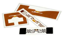
The UHF tag antennas are usually made of a copper, aluminum, or silver deposited on the substrate. Their effective length is approximately 6.5 inches, which is approximately equal to one-half the wavelength of 900 MHz radio waves. The optimum length of an UHF antenna is equal to one-half the wavelength of the carrier wave, though with proper design, the length can be reduced. The UHF antennas are thin and easy to manufacture, allowing tags to be very thin, less than 100 mM, almost two-dimensional. The UHF tags cannot be easily read while attached to objects containing water and animal tissues because water absorbs UHF waves. The UHF tags get detuned when they are attached to metal objects. Separating UHF tags from the metal objects or objects with liquid improves their performance. UHF tags cannot be read if water or any conductive material is placed between the interrogator antenna and the tags.

Example of LF Inlay
Radiative coupling used by the UHF interrogators uses radio waves to power and communicate with the tags. Reflection, diffraction, and refraction of radio waves gives rise to a multipath effect, where radio signals arrive at the receiver using multiple paths. Some of the signals from multipath attenuate the original signal. This creates an IZ with varying signal strength. The tags may not be readable in low signal spots, causing random tag readability problems. The UHF antennas are directional, which helps create an IZ with well-defined boundaries, though the zone may have holes in it. UHF tags are getting a big boost from the mandates by large organizations for their use in the supply chain. This and the creation of the Gen 2 protocol have created a tremendous momentum in RFID industry to manufacture low-cost UHF tags in high volume. UHF frequency regulations are not as uniform as HF frequency regulations. Governments in various parts of the world had assigned the UHF frequencies at around 900 MHz, long before RFID, for uses other than for RFID. Therefore, there is no common frequency range around 900 MHz available for RFID use. Different countries have different bands available with varying allowable maximum power levels and duty cycles. To overcome this problem, the Gen 2 protocol was designed to work with any frequency band within the 860–960 MHz range and with different maximum power levels. The government regulations divide the allocated frequency range into a number of narrower frequency bands. These narrower bands are called channels. Different countries have different numbers of channels available within their allocated bandwidths. The regulations also require that the interrogators do not use a single channel all the time but pseudo-randomly hop among the available channels.
The following table shows allocated band size, maximum allowable power, and number of channels allocated in a few countries. Some countries use effective isotropic radiated power (EIRP) for maximum power specifications, while the others use effective radiated power (ERP). The difference between them is discussed in Chapter 2.
| Region | BAND SIZE (MHZ) | MAXIMUM POWER | NO. OF CHANNELS |
| North America | 902–928 | 0.5–4 W EIRP | Varied |
| Europe (302–208) | 918–928 | 4 W EIRP | 50 |
| Japan | 908.5–914 | 4 W EIRP | 16 |
| Singapore | 866–869, 923–925 | 2 W ERP | 20 |
| Korea | 950–956 | 0.5 W ERP, 2 W ERP | 10 |
| Australia | 865–868 | 4 W EIRP | 12 |
| Argentina, Brazil, Peru | 902–928 | 2 W ERP | 20 |
| New Zealand | 864–929 | 4 W EIRP | 50 |
MICROWAVE TAGS
The microwave frequency range includes frequencies from 1 to 10 GHz, but only two frequency ranges around 2.45 GHz and 5.8 GHz are used for RFID applications. Almost all microwave tags use 2.45 GHz. Microwave tags are available as passive, semi-passive, and active types. The passive and semi-passive tags use backscatter coupling to communicate with interrogators, and active types use their own transmitter to communicate. Passive microwave tags are usually smaller than passive UHF tags and have the same read range of about 15 feet. The semi-passive microwave tags have a read range of about 100 feet, while the active microwave tags have read range of about 350 feet. Passive microwave tags, due to low demand, are more expensive than passive UHF tags, but they share the same advantages and disadvantages. Only a few manufacturers make this type of tag. Japan is the largest user of passive microwave tags.
Microwave antennas are directional, which helps define the IZ for passive and semi-passive tags. Due to their shorter wavelength, they are easier to design to work with metallic objects. A wider band of frequencies is available to use and more hop channels are available. However, many commonly used devices such as cordless phones and microwave ovens use this frequency. Therefore, interference at microwave frequencies is possible. Government regulations regarding use of microwave frequencies for RFID are almost nonexistent. The semi-passive microwave RFID tags are used in long-range access control for vehicles, fleet identification, and highway toll collection. Active microwave tags are used for real time location systems (RTLS).
RFID TAG CHARACTERISTICS OVERVIEW BASED ON FREQUENCY
| Frequency Bands | Antenna | Data & Speed | Read Range | Usage |
|---|---|---|---|---|
| Low Frequency (LF) 125 kHz – 134 kHz | Induction Coil on Ferrite Core, or flat many turns | Low Read Speeds – Small Ammount of Data (16 bits) | Short to Medium 3-5 feel | – Access Control – Animal Tagging – Inventory Control – Car Immobilizer |
| High Frequency (HF) 13.56 MHz | Induction Coil flat 3-9 turns | Medium Read Speed Small to Medium amounts od Data | Short 1-3 feet | – Smart Cards – Item or Case level Tagging – Proximity Cards – Vicinity Cards |
| Very High Frequency (VHF) 433 Mhz – Active Tags | Internal Custom Design | High Read Speed Large Amount of Data | High 1-1000 feet | – Asset Tracking – Locationing – Container Tracking |
| Ultra High Frequency (UHF) 860 MHz – 960 MHz | Single or Double Dipole | High Read Speed Small to Medium amount of Data | Medium 1-30 feet | – Pallet or Case Level Tagging – DOD & Walmart Mandates |
| Microwave Frequency 2.45 GHz & 5.4 GHz | Single Dipole | High Read Speed Medium Amount of Data | High 1-300 feet | – Container Rail Car – Auto Toll Roads – Pallet Level Tracking |