Define Objectives and Requirements
Before conducting a physical site survey, you must lay a strategic foundation. This step involves understanding why you need RFID, what you expect, and how it should operate.
Clarify Use Cases
Ask: What is the business goal of RFID in this location?
- Asset Tracking Do you need to know where high-value tools, IT equipment, or vehicles are in real-time or periodically?
- Inventory Management Are you trying to automate inventory counts in warehouses, stores, or production lines?
- Work-in-Progress Tracking Will RFID follow items as they move through manufacturing stages?
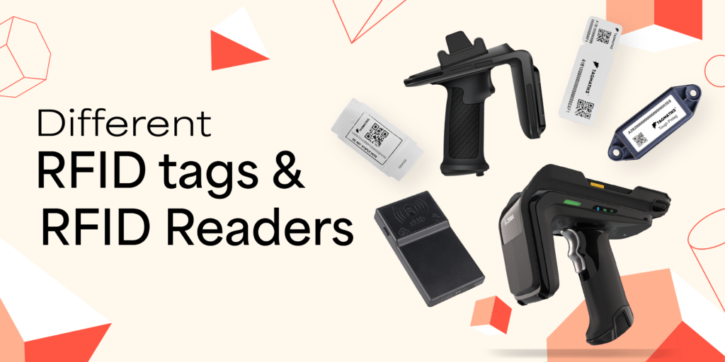
Identify RFID Tags and Readers
RFID Tags
RFID tags are attached to items or assets to transmit data wirelessly when interrogated by a reader.
Passive Tags
These tags do not contain an internal power source. Instead, they are energized by the electromagnetic field emitted by an RFID reader. They are cost-effective and suitable for high-volume applications such as inventory tracking or access control, but they offer limited read range (typically up to 10 meters) and are more sensitive to environmental conditions.
When selecting RFID tags, consider the following critical characteristics
Size and Form Factor
Tags are available in many formats such as paper-thin labels, rugged hard tags, flexible wristbands, or embeddable transponders. Choose based on the asset type, available mounting surface, and durability needs.
Surface Compatibility
Not all tags perform well on every surface. For example
- On-metal tags are specially designed to operate reliably on metallic surfaces.
- Near-liquid tags are optimized to mitigate signal interference caused by liquids.
- Embedded tags are engineered to be integrated within plastic, rubber, or wood without performance loss.
Understanding your environment and asset characteristics is vital to ensure optimal tag performance.
RFID Readers
Readers are responsible for energizing passive tags and capturing the data they transmit. They come in various configurations to serve different operational contexts
These readers are permanently mounted at strategic locations such as doorways, dock doors, conveyor belts, or production lines. They automatically read tags as they pass through the read zone, making them ideal for hands-free asset tracking, warehouse automation, and real-time visibility.
These portable readers are used by mobile workers to manually scan items or locate assets. They offer flexibility for on-demand scanning, cycle counting, and exception handling. Some include integrated barcode scanners and touchscreens, turning them into multifunctional data collection devices.
Integrated readers combine the reader, antenna, and sometimes a processor or network interface into a single compact unit. These “plug-and-play” devices are easy to deploy and are perfect for applications where space is limited or rapid installation is required. They’re commonly used in kiosks, cabinets, smart shelves, and POS systems.
When selecting RFID readers, you should also consider the read range, number of antenna ports, communication interfaces (e.g., Ethernet, Wi-Fi, Bluetooth), processing capabilities, and environmental ruggedness depending on your use case.
Define Performance Expectations
To ensure your RFID system meets operational goals and delivers consistent results, it’s essential to define quantitative performance expectations upfront. These act as measurable Key Performance Indicators (KPIs) that guide system design, deployment, and evaluation.
Key Performance Metrics to Define
- Read Range
This refers to the minimum and maximum distance at which an RFID tag must be detectable by a reader. For example:
- Short-range applications like access control may only require a read range of 3–5 feet.
- Warehouse portals or yard management systems may need read ranges of 20–30 feet or more.
- Selecting tags and readers with matching capabilities is critical to achieving the desired coverage.
Read Rate
This indicates how many tags the system can successfully read per second or per scan cycle. Applications such as conveyor belt tracking or pallet scanning require high throughput—sometimes hundreds of tags per second—while handheld scans may tolerate lower rates. A typical benchmark might be
- Handheld reader: 100–200 tags/sec.
- Fixed reader at portal: 500+ tags/sec.
Read Accuracy
Accuracy refers to the percentage of RFID tags in the field that are successfully detected during a read operation.
- For inventory tracking, a 95%+ accuracy rate may be sufficient.
- For mission-critical systems such as pharmaceutical tracking, defense, or secure access control, near 100% read accuracy is often non-negotiable.
Latency
Latency is the time between when a tag is read and when that information is updated or reflected in your system. Consider the operational impact:
- Real-time systems (e.g., live asset location dashboards or security systems) require latency under a few seconds.
- Batch processing (e.g., inventory reconciliation once per hour or shift) may tolerate higher latency. Defining latency expectations helps determine system architecture, software responsiveness, and data integration needs.
Understand Environmental Parameters
RFID system performance can vary significantly depending on the physical and environmental conditions of the deployment site. Therefore, understanding and planning for these factors is essential for hardware selection and long-term system reliability.
Key Environmental Considerations
Indoor vs. Outdoor Deployments
- Indoor environments (e.g., warehouses, retail stores, data centers) typically offer controlled conditions but may involve dense metal racking or interference from other RF systems.
- Outdoor environments (e.g., shipping yards, parking lots, construction sites) expose equipment to moisture, UV rays, wind, and temperature fluctuations. In such cases, use weather-resistant hardware with appropriate Ingress Protection (IP) ratings (e.g., IP65/IP67) to safeguard against water and dust ingress.
Temperature Extremes
- In cold storage, freezers, or refrigerated transport, standard RFID tags and readers may fail or deliver inconsistent results due to battery degradation or material contraction.
- Choose tags with wide operational temperature ranges (e.g., -40°C to +85°C), and ensure readers and enclosures are rated for the specific thermal environment.
Dust, Vibration, and Chemical Exposure
- Industrial environments such as manufacturing plants or processing facilities may contain airborne dust, mechanical vibrations, and exposure to corrosive chemicals.
- In these settings, use ruggedized readers, sealed enclosures, and industrial-grade tags designed to withstand physical shock, electromagnetic noise, and chemical contact.
Other Physical Obstacles
- Materials like metal and liquids can interfere with RFID signals. You must plan tag placement and select on-metal or liquid-tolerant tags accordingly.
- Architectural features (e.g., concrete walls, shelving) may create read blind spots or reflections—requiring thoughtful reader and antenna placement.
Analyze the Physical Environment
Understanding the physical layout and material composition of your deployment site is critical to the success of any RFID system. RF signals behave differently in real-world environments, often deviating from lab conditions due to obstacles, interference, and signal distortion. Conducting a comprehensive environmental analysis during the planning phase ensures optimal reader placement, tag selection, and system design.
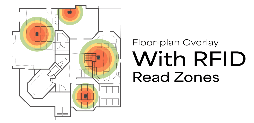
Conduct a Full Walkthrough
A thorough site walkthrough is the first step in assessing RFID feasibility. Using a floor plan as your reference, the goal is to understand how assets move through the space and how the physical layout might affect RF signal propagation.
Key Actions
Map Critical Areas
- Mark entrances and exits to track asset flow.
- Identify high-traffic zones, staging areas, receiving docks, storage aisles, packing stations, and conveyor belts.
- Include key checkpoints such as doorways, tunnels, or transition zones between departments.
Understand Workflow Direction
- Document how inventory or assets move through the facility. Are they pushed manually, transported on carts, or conveyed automatically?
- Track movement patterns across shifts—some areas may be congested at certain times, influencing signal clarity.
Document Environmental Details
- Take photos of important zones.
- Make sketches showing elevation, spacing, and shelf heights.
- Note the material composition of floors, walls, racks, ceilings, and equipment. For example:
- Metal shelving units can reflect or block RF signals.
- Glass partitions may cause unintended signal refraction.
- Concrete floors and walls can absorb or block signal strength depending on thickness.
This initial walkthrough forms the foundation for identifying risk zones and designing efficient tag and reader placements.
Identify Structural Obstacles
RFID systems are subject to signal degradation due to physical obstructions and structural interference. Identifying these challenges early will help you make informed decisions about reader type, antenna placement, and system tuning.
Common Signal Disruptors to Watch For
Blocked Signals
Dense or solid structures like reinforced concrete, metal-clad walls, and steel fire doors can prevent RF signals from passing through.
Multipath Interference
Shiny, reflective surfaces (polished metal, glass, water) can reflect signals back to the reader at different times, causing duplicate reads or false tag location data.
Signal Absorption
Materials with high moisture content, such as food products, chemicals, or wet clothing, tend to absorb RF energy, reducing read performance.
What to Document
- Wall types (e.g., drywall, cinder block, concrete), including thickness and coating.
- Rack and shelving materials, including whether they are perforated or solid.
- Obstructions such as:
- Elevators and lift shafts.
- Large metallic objects (generators, storage tanks).
- HVAC ducts, ventilation systems, and pipework.
These observations will be vital when planning read zones, antenna angles, and shielding strategies.
Note Interfering Materials
Some materials are inherently challenging for RFID technology and must be accounted for in both tag selection and system deployment. Poor understanding of these elements often leads to read failures or inconsistent performance.
Key Materials and Mitigation Strategies
Metal
- Metal reflects and detunes RFID signals. Tags mounted directly on metal surfaces must be on-metal tags, specifically engineered with protective backing and tuned antennas.
- Foam spacers, plastic brackets, or standoff mounting solutions can create necessary separation to ensure effective signal transmission.
Liquids
- Water-based substances absorb RF energy, leading to decreased signal strength.
- Place tags away from direct contact with liquid containers.
- Use specially tuned tags for applications near water or fluids (e.g., IV bags, beverage pallets).
Stacked Pallets
- Tags on the interior of tightly packed or wrapped pallets may not be readable due to tag shadowing, where the signal from one tag is blocked by adjacent materials.
- Use multiple tags per pallet or place tags on the exterior in standardized locations to mitigate this.
Other Absorptive/Interfering Materials
Rubber, dense wood, fiberglass, and thick plastic can also affect signal consistency, especially at UHF frequencies.
Why This Matters
Documenting these challenges enables you to:
- Choose the right RFID tags (on-metal, encapsulated, moisture-resistant, etc.).
- Adjust antenna type, power levels, and orientation to minimize interference.
- Avoid costly system redesigns post-installation.
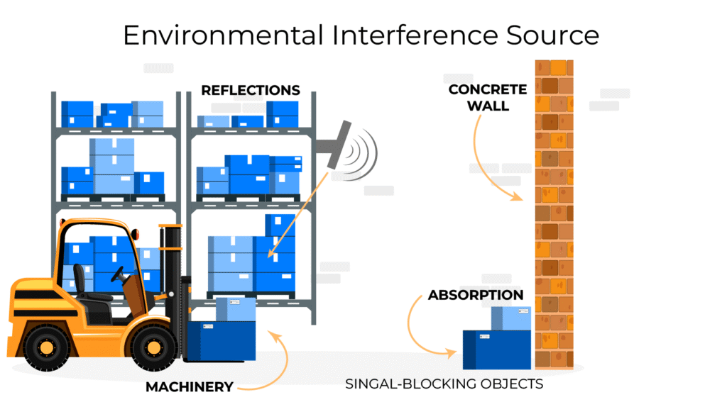
Check for RF Interference
RFID systems rely on clean, predictable radio frequency (RF) environments to function reliably. However, in real-world deployments, various electronic devices and machinery may emit radio waves that interfere with RFID signals. Identifying and mitigating these sources of interference is crucial for maintaining consistent tag readability, minimizing missed reads, and avoiding performance degradation—especially in complex or high-density deployments.
Identify Interfering Devices
Many modern facilities operate a wide range of wireless technologies and industrial equipment, some of which may share frequencies with RFID systems or emit electromagnetic noise that disrupts RF communication. These sources can interfere with both the readers and the tags—especially in UHF (Ultra High Frequency) environments.
Common Sources of RF Interference Include
Wi-Fi Routers and Access Points
Particularly those operating in the 900 MHz band (some IoT Wi-Fi modules) or the 2.4 GHz band (which may overlap with some RFID systems or interfere with integrated IoT-RFID platforms).
Bluetooth Devices
Bluetooth operates in the 2.4 GHz band and can create congestion or noise for RFID systems running in the same band (e.g., HF RFID at 13.56 MHz is less affected, but UHF with BLE integrations may experience conflict).
Cordless Phones, Baby Monitors, Wireless Headsets
These consumer-grade devices, especially those operating on the same spectrum as UHF RFID (902–928 MHz in North America), may emit strong signals or harmonics that overlap with RFID communication bands.
Industrial Equipment and Motors
Equipment like frequency converters, variable frequency drives (VFDs), welding machines, HVAC systems, and arc furnaces can generate substantial electromagnetic interference (EMI), which can severely disrupt RFID read zones.
Microwave Ovens and Fluorescent Ballasts
These can emit broad-spectrum RF noise and are often overlooked as contributors to poor RFID performance.
The Risk
These devices may:
- Reduce read range (by raising the noise floor),
- Cause intermittent tag detection,
- Or create dead zones, particularly in environments with many tags, fast movement, or metallic reflections.
Use Spectrum Analyzers
To accurately assess and visualize RF interference in your environment, it’s essential to use a spectrum analyzer. This tool captures a real-time view of RF energy across a selected frequency band and reveals both continuous and intermittent sources of interference.
What a Spectrum Analyzer Helps You Detect
Baseline Noise Levels
Evaluate the general signal-to-noise ratio in the RFID operating band (e.g., 902–928 MHz for UHF in North America, or 865–868 MHz in Europe). Higher noise levels reduce the reader’s ability to distinguish tag responses.
Frequency Spikes and Disruptions
Identify specific frequencies experiencing sudden spikes or erratic patterns, often indicating the presence of disruptive equipment or co-channel interference.
Time-Varying Interference
Some machines emit RF noise only during specific cycles—such as startup, shutdown, or maintenance. These intermittent signals may go unnoticed without long-duration or repeated spectrum scans.
Best Practices for Spectrum Analysis
Scan at Different Times
Conduct scans during various operational conditions, including:
- Peak production hours (when most equipment is running),
- Machine startup/shutdown windows (to detect surge-related EMI),
- Maintenance activities (when tools like welders or diagnostics equipment are active).
Scan at Different Locations
Perform analysis in each planned RFID read zone—such as entry/exit portals, conveyor stations, and storage aisles—to catch localized interference.
Log and Compare Results
Store readings to identify patterns over time and detect whether interference is transient or persistent.
Tag and Reader Testing (Bench & Field Tests)
You must validate RFID tag and reader performance before full deployment.
Tag Testing
Evaluate:
- Read distance for each tag type.
- How orientation affects detection (tags aligned with antenna polarity vs not).
- Consistency across multiple readings and environmental conditions.
- Behavior when near metals or liquids.
Test tags on actual items to replicate real-world use cases, including boxed or stacked products.
Reader Testing
Use handheld readers or test setups to determine:
- Range with specific tag types.
- Ability to detect multiple tags at once (anti-collision performance).
- Performance when tags are moving, such as on a conveyor.
- Reader sensitivity settings and how power level affects detection.
Document the exact reader model, firmware, and antenna used in tests.
Conduct Readability Tests in Real Conditions
Simulating real-world scenarios is essential for determining system reliability.
Simulate Reader Zones
Examples:
- Place antennas at dock doors, simulate pallet movement.
- Mount readers above shelves for inventory scans.
- Set up side antennas at gates for personnel/vehicle tracking.
Test varied configurations, including different:
- Antenna angles and positions.
- Heights and mounting distances.
- Read power levels.
Measure Metrics
Capture:
- Tag Detection Rate: Out of 100 tags, how many are read consistently?
- Read Range: When does the tag enter/leave detection zone?
- Signal Stability: Are tags dropping out randomly?
- Multi-tag Read Behavior: Do all tags on a pallet get detected equally?
Look for “null zones” – spots where tag reads fail due to destructive signal interference or poor orientation.
Evaluate Power and Network Availability
Check Power Infrastructure
- PoE (Power over Ethernet): Allows power and data to be delivered through a single Ethernet cable, simplifying installations.
- Dedicated AC power outlets: Standard electrical outlets are needed if PoE isn’t supported by the reader.
- Verify Outlet locations: Ensure power outlets are located close enough to where RFID readers will be installed.
- Cable run feasibility: Check if it’s practical to run cables between power sources and RFID equipment.
- Surge protection or UPS needs: Protect equipment from voltage spikes and provide backup power during outages.
- Weatherproof power enclosures (for outdoor systems): Use sealed, outdoor-rated enclosures to protect power connections from rain, dust, and extreme temperatures.
Assess Network Access
- Ethernet availability: Ensure there are Ethernet ports nearby to provide wired network access to RFID readers.
- Wi-Fi coverage and strength: Test Wi-Fi signal strength to confirm reliable wireless connectivity for RFID devices.
- Firewall settings or IP blocking: Check network configurations to ensure RFID readers can communicate through the firewall.
- Cellular signal strength for LTE-enabled readers: Measure signal strength to ensure stable mobile network communication where used.
- Plan the data routing topology: Decide whether RFID data will be processed locally on a server or sent to a cloud platform for centralized access.
Optimize Antenna Placement and Orientation
Select Appropriate Antennas
- Omni-directional antennas: Cover wide areas, used for general zone coverage.
- Directional antennas: Focused beam for accuracy, ideal for chokepoints and portals.
- Circular-polarized antennas: Work well with varied tag orientations.
Choose based on tag movement patterns and required coverage area.
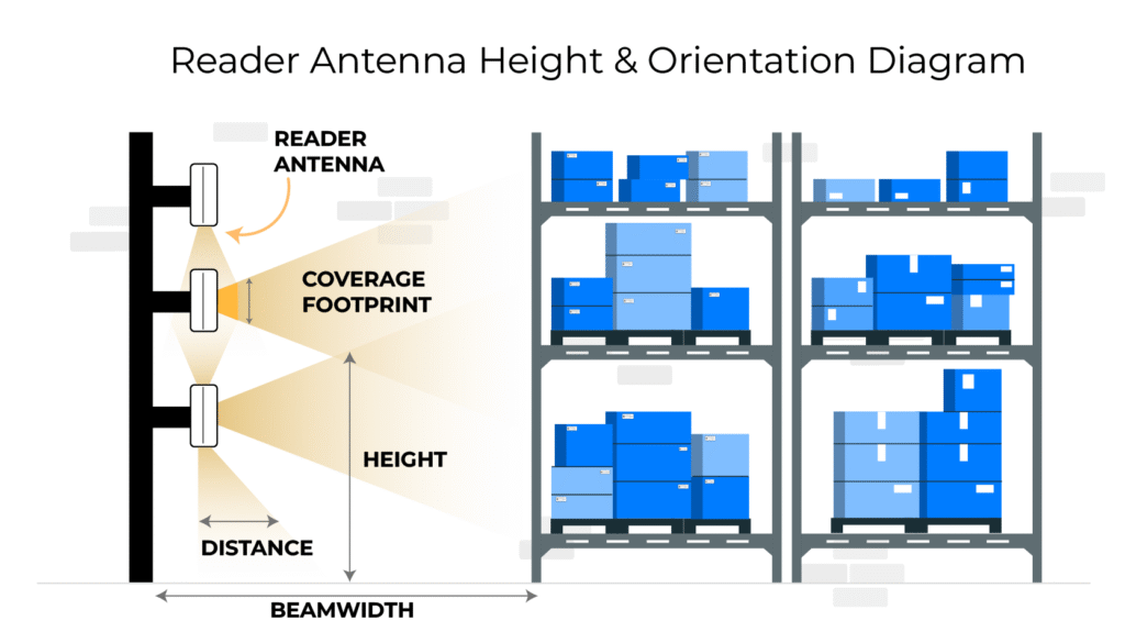
Mount and Adjust
Experiment with:
- Height: Mounting antennas too high or low may miss tags.
- Angle: A slight downward tilt helps maximize read coverage on moving items.
- Spacing: Prevent read zone overlaps which cause duplicated reads.
Use a grid testing pattern to map signal strength throughout an area.
Document Findings and Create a Deployment Plan
Create Visual Maps
- Proposed antenna locations: Show exactly where each RFID antenna will be installed for optimal coverage.
- Cable routing (Ethernet, power): Map the planned paths for network and power cables to ensure feasibility and organization.
- Interference zones: Highlight areas with potential signal disruption (e.g., metal structures, machinery).
- Storage zones, docks, gates: Identify operational areas where tracking is critical to guide equipment placement.
- Label everything: distances, angles, equipment types: Provide precise details to guide installers and reduce setup errors.
Prepare a Comprehensive Report
- Summary of all tests: Document results from site surveys, including read range and signal strength evaluations.
- Best-performing tag and reader combinations: Highlight the most effective RFID tag-reader pairs for your environment.
- Recommended equipment SKUs: List exact models and part numbers to streamline purchasing and deployment.
- Power and network plans: Include diagrams and notes on how devices will be powered and connected to your network.
- Final antenna positions and configurations: Lock in the optimal setup based on testing and site layout.
- Risk mitigation for interference or blind spots: Suggest solutions for minimizing read errors and improving reliability.
Pilot and Validate
Small-Scale Pilot
- Choose a controlled environment (e.g., one door or aisle): Start in a limited area to minimize variables and control testing conditions.
- Install readers and tags: Set up RFID hardware as planned to simulate real-world usage.
- Run real transactions (e.g., inbound shipments): Test the system with actual workflow scenarios to assess performance.
- Observe employee interaction with hardware: Watch how staff use the system to identify usability issues or training needs.
Evaluate Results
- Are read rates meeting expectations?: Check if the system is consistently capturing tag reads with high accuracy.
- Is data flowing to your application or ERP correctly?: Confirm that RFID data is being transmitted and integrated into backend systems properly.
- Are users able to operate the system efficiently?: Assess whether employees can use the system smoothly without confusion or delays.
Iterate and Finalize
Adjust Based on Pilot
- Reposition antennas for better coverage: Move antennas to eliminate blind spots or weak read areas identified during the pilot.
- Replace underperforming tags: Swap out tags that had poor read performance with more suitable options.
- Tune reader power settings: Adjust signal strength to reduce interference or extend range as needed.
- Address software/data flow issues: Fix any problems in how data moves between readers, middleware, and backend systems.
Final Rollout
- Once tuned, expand to the full facility: Scale the optimized setup across all areas, based on successful pilot adjustments.
- Use installation drawings and test data to guide deployment: Follow documented maps and configurations for consistent results.
- Train users on system operation: Educate staff on how to use the system effectively for daily tasks.
- Monitor performance for the first 2–4 weeks: Closely track system behavior to catch any issues early and fine-tune if needed.
Perform post-installation audit to ensure nothing was missed.
Tools Checklist
| Tool | Purpose |
|---|---|
| Handheld RFID Reader | Tag/antenna testing |
| Spectrum Analyzer | RF interference detection |
| RFID Tags (various) | Performance comparison |
| Measuring Tape, Ladder | Antenna setup |
| Laptop with Software | Data analysis and logging |
| Floor Plan Maps | Visualization of layouts |